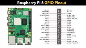
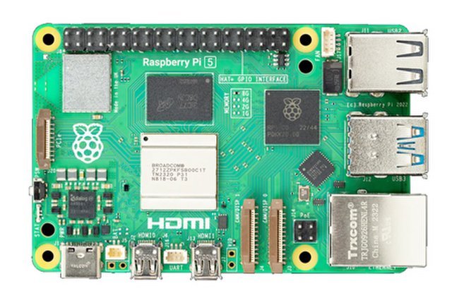
If you’ve just unboxed your shiny new Raspberry Pi 5, one of the first things you’ll notice is that familiar 40-pin header sitting proudly on the board. That’s the GPIO header — basically your Pi’s way of talking to the outside world.
GPIO stands for General Purpose Input/Output, and these pins let you connect all kinds of components: sensors, LEDs, buttons, motors, displays, and a lot more. Whether you’re building a simple LED blink project or a full-blown home automation system, you’ll be using these pins a lot.
What makes GPIO pins special is their flexibility. Some can be set as input to read data from a sensor or button. Others can act as output to control things like LEDs, relays, or servos. And a few pins have special functions like I²C, SPI, and UART that let you communicate with more advanced modules and devices.
But here’s the thing—not all pins are the same, and using the wrong one can mess up your project (or worse, your Pi). That’s why knowing the GPIO pinout is super important. It’s like having a map before heading out on a road trip.
In this guide, we’ll break down the Raspberry Pi 5 GPIO pinout in a beginner-friendly way. We’ll look at what each pin does, what’s new in Pi 5, and how you can actually use these pins in real projects. By the end, you’ll have a clear picture of how to wire things up safely and confidently.
Overview of the RPI 5 GPIO Pinout
Let’s get familiar with the heart of it all — that 40-pin GPIO header on Raspberry Pi 5.
Even though the Pi 5 is newer and more powerful, the header layout is still very similar to previous models like Raspberry Pi 4 Model B. That’s great news because most accessories, HATs, and sensor modules will work just like before.
Each of these 40 pins has a specific role — some provide power, some act as ground, and the rest can be used as digital input/output or for communication protocols like I²C, SPI, or UART. Think of it as your Pi’s “multi-purpose connector.”
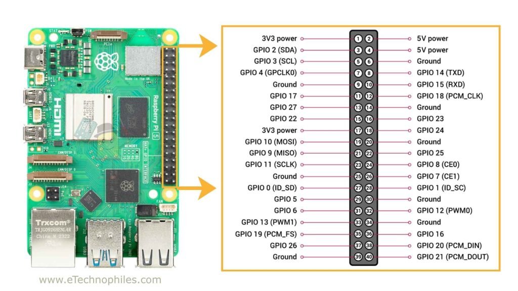
Physical vs Chip numbering
Imp: Please note that there are two ways to refer to the GPIO pins.
- Physical numbering: This is simply pin 1 to pin 40, counting down the rows physically on the header.
- BCM numbering (Broadcom chip): This refers to the internal GPIO numbers of the Pi’s processor.
For example, pin 11 on the physical header is GPIO 17 in BCM numbering.
When writing code (especially in Python), you can use either system — but you have to be consistent, or your code won’t behave as expected.
Most diagrams and tutorials use physical numbering for wiring and BCM numbering in code. It’s good to get used to both early on.
RPi 5 Pin categories & functions
| Pin | Name | Type | Function |
| 1 | 3V3 | Power | 3.3V Power |
| 2 | 5V | Power | 5V Power |
| 3 | GPIO2 | I2C | Serial Data (SDA) |
| 4 | 5V | Power | 5V Power |
| 5 | GPIO3 | I2C | Serial Clock (SCL) |
| 6 | GND | Ground | Ground |
| 7 | GPIO4 | GPIO | General Purpose I/O |
| 8 | GPIO14 | UART | Transmit (TXD) |
| 9 | GND | Ground | Ground |
| 10 | GPIO15 | UART | Receive (RXD) |
| 11 | GPIO17 | SPI | Chip Enable 1 (CE1) |
| 12 | GPIO18 | PWM | General Purpose I/O |
| 13 | GPIO27 | GPIO | General Purpose I/O |
| 14 | GND | Ground | Ground |
| 15 | GPIO22 | GPIO | General Purpose I/O |
| 16 | GPIO23 | GPIO | General Purpose I/O |
| 17 | 3V3 | Power | 3.3V Power |
| 18 | GPIO24 | GPIO | General Purpose I/O |
| 19 | GPIO10 | SPI0 | MOSI (Master Out Slave In) |
| 20 | GND | Ground | Ground |
| 21 | GPIO9 | SPI0 | MISO (Master In Slave Out) |
| 22 | GPIO25 | GPIO | General Purpose I/O |
| 23 | GPIO11 | SPI0 | Serial Clock (SCLK) |
| 24 | GPIO8 | SPI0 | Chip Enable 0 (CE0) |
| 25 | GND | Ground | Ground |
| 26 | GPIO7 | SPI0 | Chip Enable 1 (CE1) |
| 27 | GPIO0 | I2C | EEPROM Serial Data (SDA) |
| 28 | GPIO1 | I2C | EEPROM Serial Clock (SCL) |
| 29 | GPIO5 | GPIO | General Purpose I/O |
| 30 | GND | Ground | Ground |
| 31 | GPIO6 | GPIO | General Purpose I/O |
| 32 | GPIO12 | PWM | General Purpose I/O |
| 33 | GPIO13 | PWM | General Purpose I/O |
| 34 | GND | Ground | Ground |
| 35 | GPIO19 | SPI1 | MISO (Master In Slave Out) |
| 36 | GPIO16 | SPI1 | Chip Enable 2 (CE2) |
| 37 | GPIO26 | GPIO | General Purpose I/O |
| 38 | GPIO20 | SPI1 | MOSI (Master Out Slave In) |
| 39 | GND | Ground | Ground |
| 40 | GPIO21 | SPI1 | Serial Clock (SCLK) |
Here’s a quick breakdown of what kinds of pins you’ll find:
- Power pins → 5 V and 3.3 V output pins to power your components.
- Ground pins (GND) → these complete the circuit.
- Standard GPIO pins → general-purpose pins for input/output.
- Special function pins → used for I²C, SPI, UART, and PCM communications.
1. Power pins (5 V and 3.3 V)
- These pins provide power directly from the Pi’s power supply.
- 5 V pins (Pins 2 and 4) can power components like relays, LED strips, and certain sensors.
- 3.3 V pins (Pins 1 and 17) are used for most low-voltage sensors and modules.
Note: GPIO logic runs at 3.3 V — not 5 V. So if you connect 5 V directly to a GPIO pin, there’s a good chance you’ll fry your board. If your component needs 5 V but communicates at 3.3 V, use a logic level shifter.
2. Ground pins (GND)
- Ground pins are your circuit’s return path.
- They’re located on multiple pins across the header (Pins 6, 9, 14, 20, 25, 30, 34, and 39).
3. Standard GPIO pins
- These are the “do anything” pins. You can set them as input (to read from a button, sensor, etc.) or output (to control LEDs, buzzers, relays, etc.).
- Each GPIO pin can be programmed individually.
For example, you can set GPIO 17 (Physical Pin 11) to output HIGH, and your LED will turn on. Set it to LOW, and the LED turns off. Simple as that.
4. Special function pins
Some pins can do more than just act as regular input/output. These are used for communication protocols that let the Pi talk to other chips and modules.
Here are the main ones:
- I²C (Inter-Integrated Circuit)
- Used to connect sensors and modules that support I²C (like temperature sensors, OLED displays, etc.).
- Pins: SDA (Pin 3, GPIO 2) and SCL (Pin 5, GPIO 3).
- SPI (Serial Peripheral Interface)
- A fast communication protocol often used for displays and memory modules.
- Pins: MISO (Pin 21), MOSI (Pin 19), SCLK (Pin 23), CE0 (Pin 24), CE1 (Pin 26).
- UART (Universal Asynchronous Receiver/Transmitter)
- Used for serial communication, like connecting the Pi to an Arduino or a GPS module.
- Pins: TX (Pin 8, GPIO 14) and RX (Pin 10, GPIO 15).
- PCM / I2S (Pulse-code modulation)
- Useful for audio projects and digital sound interfaces.
- These pins overlap with some SPI pins, so you can’t use both at the same time on the same pins.
Note: Many special function pins overlap with standard GPIO pins. That means you can either use them for their special function or as a regular GPIO, but not both at once.
What’s new in Raspberry Pi 5 GPIO
The biggest change is that the GPIO pins are no longer handled directly by the main CPU. Instead, they’re managed by the new RP1 I/O controller chip.
This chip takes care of USB, PCIe, camera/display connectors, and yes — all GPIO functions. This shift gives the Pi 5 better performance and more consistent timing for things like I²C and SPI.
For most beginners, this doesn’t change how you wire things up, but it does affect the software side a bit (especially if you’re used to older libraries).
In older models, GPIO pins were accessed via gpiochip0 in Linux.
On the Pi 5, they’re now under /dev/gpiochip4.
So if you’re using libraries that interact directly with GPIO devices (like gpiod in Python or C), you’ll need to update your code accordingly.
But even with all these internal upgrades, the pinout itself hasn’t changed. That means if your HATs, sensors, or breadboard circuits worked on a Pi 4, they’ll almost certainly work on a Pi 5 too — as long as your software supports the new GPIO controller.
Conclusion
That’s pretty much everything you need to know about the GPIO pins on the Raspberry Pi 5.
The layout hasn’t changed much, so if you’ve used older Pis before, you’ll feel right at home. The only real difference is what’s happening behind the scenes with the new RP1 chip.
Just keep a few things in mind:
- Double-check your wiring.
- Don’t put 5 V into a 3.3 V pin.
- Keep a pinout chart nearby.
Once you get comfortable with these pins, building projects gets a lot easier (and a lot more fun).