
In this article, I have discussed 10 ESP32 concepts that actually matter when building real projects. Each concept is explained with a practical example, showing not just what the ESP32 can do, but how to use those features correctly. If you already know the basics and want to build faster, smoother, and more reliable projects, this will take you there step by step.
Table of Contents
Number 1: Using the dual cores
The first thing you need to know is that the ESP32 isn’t just a regular microcontroller, it actually has two processing cores. That means it can literally do two things at once.
For example, you could dedicate one core to handling Wi-Fi and the other core to reading sensor data, so your project runs much smoother. This is a huge advantage over boards like the Arduino Uno, which only has a single-core processor.
Please note that by default the programs are run on core 1.
Here’s a simple demo showing how to use the other core:
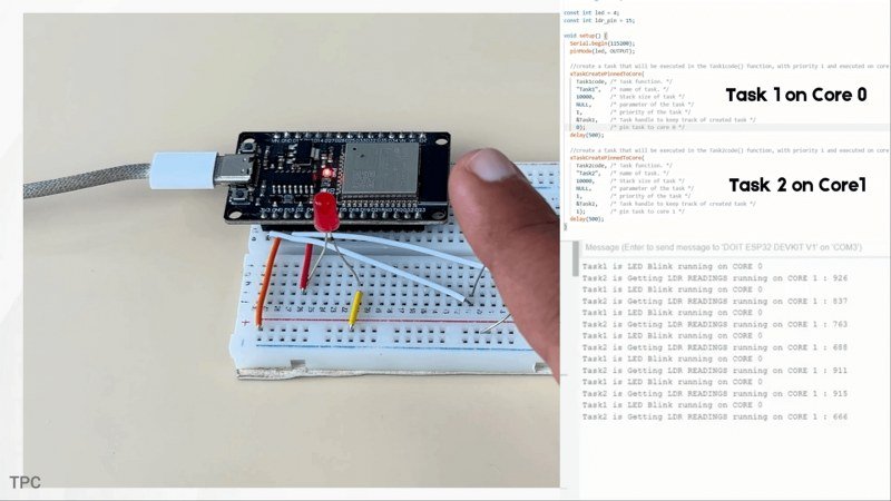
In this project, ESP32 is blinking the LED with 1 second delay, and reading LDR sensor values running on different cores. On the serial monitor you can see which core is performing which function: the task1 is LED Blink running on core0 and task2 is getting LDR readings running on Core1.
Because each task is assigned to its own CPU core, both tasks run independently and simultaneously, without interrupting each other.
You can learn more about this feature in this article.
Code:
TaskHandle_t Task1;
TaskHandle_t Task2;

const int led = 4;
const int ldr_pin = 15;

void setup() {
  Serial.begin(115200);
  pinMode(led, OUTPUT);

  //create a task that will be executed in the Task1code() function, with priority 1 and executed on core 0
  xTaskCreatePinnedToCore(
    Task1code, /* Task function. */
    "Task1",   /* name of task. */
    10000,     /* Stack size of task */
    NULL,      /* parameter of the task */
    1,         /* priority of the task */
    &Task1,    /* Task handle to keep track of created task */
    0);        /* pin task to core 0 */
  delay(500);

  //create a task that will be executed in the Task2code() function, with priority 1 and executed on core 1
  xTaskCreatePinnedToCore(
    Task2code, /* Task function. */
    "Task2",   /* name of task. */
    10000,     /* Stack size of task */
    NULL,      /* parameter of the task */
    1,         /* priority of the task */
    &Task2,    /* Task handle to keep track of created task */
    1);        /* pin task to core 1 */
  delay(500);
}

//Task1code: blinks an LED every 1000 ms
void Task1code(void* pvParameters) {

  for (;;) {
    Serial.print("Task1 is LED Blink running on CORE ");
    Serial.println(xPortGetCoreID());
    digitalWrite(led, HIGH);
    delay(1000);
    digitalWrite(led, LOW);
    delay(1000);
  }
}

//Task2code: Get sensor readings evey 2 seconds
void Task2code(void* pvParameters) {

  for (;;) {
    Serial.print("Task2 is Getting LDR READINGS running on CORE ");
    Serial.print(xPortGetCoreID());
    Serial.print(" : ");
    Serial.println(analogRead(ldr_pin));
    delay(2000);
  }
}

void loop() {
}
Number 2: Running multiple tasks with FreeRTOS
Most people only use the ESP32 with a single loop() function, but here’s the secret, under the hood, it actually runs on FreeRTOS, a real-time operating system. This lets you create multiple tasks that run independently, instead of cramming everything into one loop.
Now, you might be wondering, isn’t this the same as interrupts, or just using both cores? Not really.
Interrupts are quick reactions to events, and dual-core only gives you two processors. FreeRTOS is like a task manager — it schedules tasks and switches between them so fast it feels like they’re happening at the same time, even on a single core. And when combined with the ESP32’s dual-core architecture, it becomes really powerful.
Here’s a simple example. I created three FreeRTOS tasks:
- Task A blinks the RED LED every 1000 milliseconds,
- Task B blinks the Blue LED every 2000 milliseconds.
- Task C blinks the Yellow LED every 3000 milliseconds.
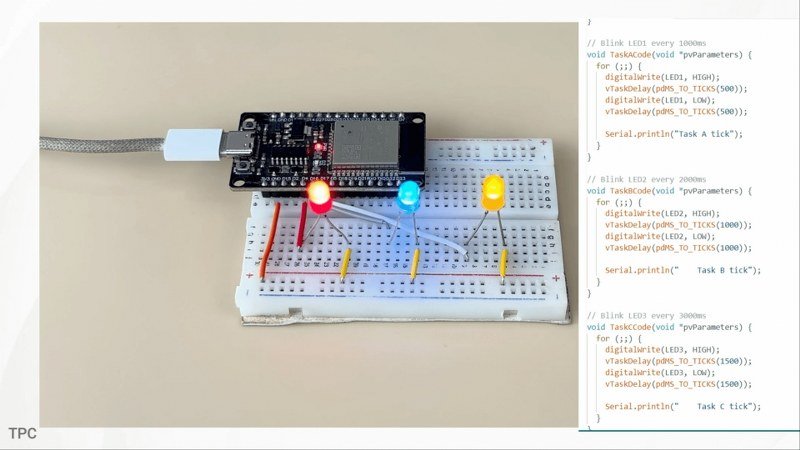
Now all three are running on the same core, no dual-core use, no interrupts. as you can see in the program as well. And if you look closely the LED are all blinking at different speeds, at the same time. That’s FreeRTOS. It switches between tasks extremely fast, so they look like they’re happening in parallel.
Code:
TaskHandle_t TaskA;
TaskHandle_t TaskB;
TaskHandle_t TaskC;

const int LED1 = 4;
const int LED2 = 16;
const int LED3 = 17;

void setup() {
  Serial.begin(115200);
  pinMode(LED1, OUTPUT);
  pinMode(LED2, OUTPUT);
  pinMode(LED3, OUTPUT);

  Serial.println("FreeRTOS parallel demo (both tasks on same core)");

  xTaskCreate(
    TaskACode,
    "Task A",
    2048,
    NULL,
    1,
    &TaskA
  );

  xTaskCreate(
    TaskBCode,
    "Task B",
    2048,
    NULL,
    1,
    &TaskB
  );

    xTaskCreate(
    TaskCCode,
    "Task C",
    2048,
    NULL,
    1,
    &TaskC
  );
}

// Blink LED1 every 1000ms
void TaskACode(void *pvParameters) {
  for (;;) {
    digitalWrite(LED1, HIGH);
    vTaskDelay(pdMS_TO_TICKS(500));
    digitalWrite(LED1, LOW);
    vTaskDelay(pdMS_TO_TICKS(500));

    Serial.println("Task A tick");
  }
}

// Blink LED2 every 2000ms
void TaskBCode(void *pvParameters) {
  for (;;) {
    digitalWrite(LED2, HIGH);
    vTaskDelay(pdMS_TO_TICKS(1000));
    digitalWrite(LED2, LOW);
    vTaskDelay(pdMS_TO_TICKS(1000));

    Serial.println("    Task B tick");
  }
}

// Blink LED3 every 3000ms
void TaskCCode(void *pvParameters) {
  for (;;) {
    digitalWrite(LED3, HIGH);
    vTaskDelay(pdMS_TO_TICKS(1500));
    digitalWrite(LED3, LOW);
    vTaskDelay(pdMS_TO_TICKS(1500));

    Serial.println("    Task C tick");
  }
}


void loop() {}
Number 3: Using the ESP-NOW protocol
ESP-NOW is hands-down the best feature you get with the ESP32 board. It’s a communication protocol developed by Espressif that lets multiple ESP32 boards talk to each other directly without Wi-Fi, without a router, and with extremely low power consumption.
Here’s a simple demo using just two ESP32 boards.
The first ESP32 reads analog values from a connected potentiometer and sends them to the second ESP32 using the ESP-NOW protocol. The second ESP32 receives the data and adjusts the LED brightness based on the received value.
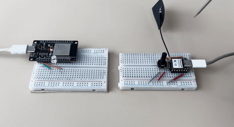
There’s no Wi-Fi connection here, no router, no pairing process, just instant device-to-device communication. And the power consumption stays incredibly low because the radios only wake up for a fraction of a second to send each packet.
Code (Sender board):
#include <esp_now.h>
#include <WiFi.h>

#define POT_PIN A0

uint8_t broadcastAddress[] = {0x3C,0x8A,0x1F,0xB0,0x5B,0x50};

typedef struct {
  uint16_t potValue;
} DataPacket;

DataPacket data;

void setup() {
  Serial.begin(115200);

  WiFi.mode(WIFI_STA);

  if (esp_now_init() != ESP_OK) {
    Serial.println("ESP-NOW init failed");
    return;
  }

  esp_now_peer_info_t peerInfo = {};
  memcpy(peerInfo.peer_addr, broadcastAddress, 6);
  peerInfo.channel = 0;
  peerInfo.encrypt = false;

  esp_now_add_peer(&peerInfo);
}

void loop() {
  data.potValue = analogRead(POT_PIN);

  esp_now_send(broadcastAddress,
               (uint8_t*)&data,
               sizeof(data));

  Serial.println(data.potValue);
  delay(50);
}
Code (Receiver board):
#include <esp_now.h>
#include <WiFi.h>

#define LED_PIN 15

typedef struct {
  uint16_t potValue;
} DataPacket;

DataPacket data;

// NEW callback signature for ESP32 core 3.x / IDF v5
void onDataReceive(const esp_now_recv_info_t *recv_info,
                   const uint8_t *incomingData,
                   int len) {
  memcpy(&data, incomingData, sizeof(data));
  Serial.println(data.potValue);
  int pwmValue = map(data.potValue, 0, 4095, 0, 255);
  Serial.println(pwmValue);
  analogWrite(LED_PIN,pwmValue);
}

void setup() {
  Serial.begin(115200);

  WiFi.mode(WIFI_STA);

  // NEW LEDC API
  //ledcAttach(LED_PIN, PWM_FREQ, PWM_RESOLUTION);
  //ledcWrite(PWM_CHANNEL, 0);

  if (esp_now_init() != ESP_OK) {
    Serial.println("ESP-NOW init failed");
    return;
  }

  // REGISTER RECEIVE CALLBACK (new signature)
  //esp_now_register_recv_cb(onDataReceive);
  esp_now_register_recv_cb(esp_now_recv_cb_t(onDataReceive));
}

void loop() {

}
Number 4: Using the Async Webserver
One of the most popular things people do with the ESP32 is create a web interface to control sensors, LEDs, motors, and more.
But the basic web server that most tutorials use is blocking, meaning while the ESP32 is busy serving a webpage or handling a request, the main loop pauses and nothing else can run.
That’s where the Async Web Server comes in.
The Async server handles all web requests in the background, without stopping your main code. Your ESP32 can keep reading sensors, updating values, and reacting to inputs while the webpage is being served.
And when you combine this with WebSockets, you can update sensors, graphs, and controls on your webpage in real time, without reloading the page. This is the same technology used in modern IoT dashboards, and it makes your ESP32 projects feel smooth, fast, and professional.
Here’s a simple example: I connected a potentiometer to the ESP32 and created a small real-time dashboard. As I turn the knob, the value updates instantly on the webpage using WebSockets without needing a page refresh and without any lag.
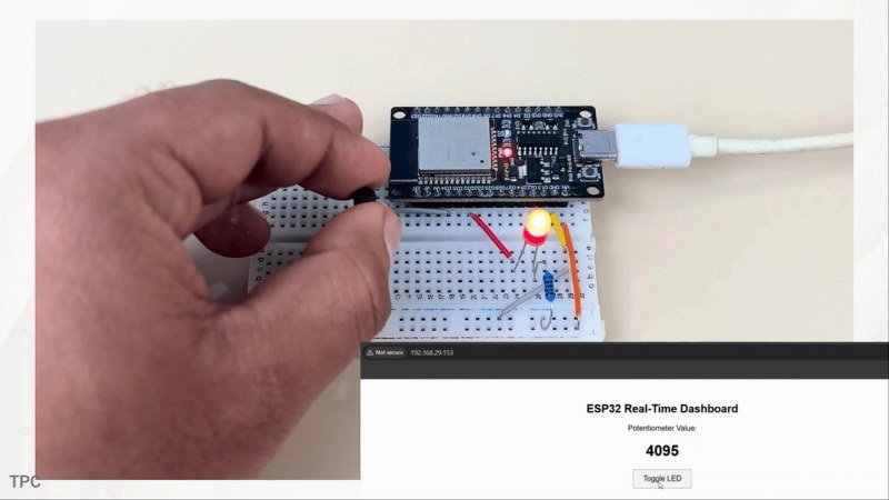
At the same time, I can toggle an LED from the dashboard, and the ESP32 reacts immediately. This works because the Async server handles web communication in the background, while the ESP32’s main loop keeps running continuously.
You can learn more about this feature in this GitHub repository.
Code:
#include <WiFi.h>
#include <AsyncTCP.h>
#include <ESPAsyncWebServer.h>

// Replace with your network credentials
const char* ssid = "...................";
const char* password = "......................";

#define POT_PIN 34
#define LED_PIN 32

AsyncWebServer server(80);
AsyncWebSocket ws("/ws");

String potValue = "0";

// HTML + JavaScript
const char index_html[] PROGMEM = R"rawliteral(
<!DOCTYPE html>
<html>
<head>
  <title>ESP32 Real-Time Dashboard</title>
  <style>
    body { font-family: Arial; text-align: center; margin-top: 50px; }
    button { padding: 10px 20px; font-size: 16px; }
  </style>
</head>
<body>

<h2>ESP32 Real-Time Dashboard</h2>

<p>Potentiometer Value:</p>
<h1 id="pot">0</h1>

<button onclick="toggleLED()">Toggle LED</button>

<script>
let ws = new WebSocket(`ws://${location.host}/ws`);

ws.onmessage = (event) => {
  document.getElementById("pot").innerHTML = event.data;
};

function toggleLED() {
  ws.send("toggle");
}
</script>

</body>
</html>
)rawliteral";

// Handle WebSocket events
void onWebSocketEvent(AsyncWebSocket *server,
                      AsyncWebSocketClient *client,
                      AwsEventType type,
                      void *arg,
                      uint8_t *data,
                      size_t len) {

  if (type == WS_EVT_DATA) {
    String msg = "";
    for (int i = 0; i < len; i++) {
      msg += (char)data[i];
    }

    if (msg == "toggle") {
      digitalWrite(LED_PIN, !digitalRead(LED_PIN));
    }
  }
}

void setup() {
  Serial.begin(115200);

  pinMode(LED_PIN, OUTPUT);
  digitalWrite(LED_PIN, LOW);

  WiFi.begin(ssid, password);
  Serial.print("Connecting to WiFi");

  while (WiFi.status() != WL_CONNECTED) {
    delay(500);
    Serial.print(".");
  }

  Serial.println("\nWiFi connected");
  Serial.print("ESP32 IP: ");
  Serial.println(WiFi.localIP());

  ws.onEvent(onWebSocketEvent);
  server.addHandler(&ws);

  server.on("/", HTTP_GET, [](AsyncWebServerRequest *request) {
    request->send_P(200, "text/html", index_html);
  });

  server.begin();
}

void loop() {
  int pot = analogRead(POT_PIN);
  potValue = String(pot);

  ws.textAll(potValue);   // Push value instantly to browser
  delay(100);
}
Number 5: Uploading a code OTA (Over the air)
This feature allows you to upload a program to ESP32 board over the air without any serial communication.
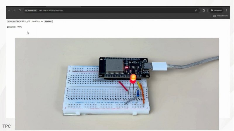
Here are the steps to do it:
- First open the OTAwebserver example from files-> examples->ArduinoOTA.
- Upload the code to your ESP32 board. Make sure to add your network credentials before uploading.
- Next open the serial monitor and copy the IP address assigned to your ESP32.
- Paste it in your browser. Enter your username and password- both set to admin by default. You can change them from here in the program.
After you have logged in successfully, you can directly upload the code from here. But there’s a catch.
- In order to update or upload new sketch over the air, you need to include the previous ArduinoOTA code every time.
- Secondly, the sketch file should be in .bin extension. You can generate the bin version of your program by going to Sketch and export compiled binary.
You can now upload the file by selecting it and clicking Update, and it will be running on your ESP32 in no time.
#include <WiFi.h>
#include <WiFiClient.h>
#include <WebServer.h>
#include <ESPmDNS.h>
#include <Update.h>

const int LED = 32;

const char* host = "esp32";
// Replace with your network credentials
const char* ssid = "...........................";
const char* password = "..............................";

WebServer server(80);


const char* loginIndex =
 "<form name='loginForm'>"
    "<table width='20%' bgcolor='A09F9F' align='center'>"
        "<tr>"
            "<td colspan=2>"
                "<center><font size=4><b>ESP32 Login Page</b></font></center>"
                "<br>"
            "</td>"
            "<br>"
            "<br>"
        "</tr>"
        "<tr>"
             "<td>Username:</td>"
             "<td><input type='text' size=25 name='userid'><br></td>"
        "</tr>"
        "<br>"
        "<br>"
        "<tr>"
            "<td>Password:</td>"
            "<td><input type='Password' size=25 name='pwd'><br></td>"
            "<br>"
            "<br>"
        "</tr>"
        "<tr>"
            "<td><input type='submit' onclick='check(this.form)' value='Login'></td>"
        "</tr>"
    "</table>"
"</form>"
"<script>"
    "function check(form)"
    "{"
    "if(form.userid.value=='admin' && form.pwd.value=='admin')"
    "{"
    "window.open('/serverIndex')"
    "}"
    "else"
    "{"
    " alert('Error Password or Username')/*displays error message*/"
    "}"
    "}"
"</script>";


const char* serverIndex =
"<script src='https://ajax.googleapis.com/ajax/libs/jquery/3.2.1/jquery.min.js'></script>"
"<form method='POST' action='#' enctype='multipart/form-data' id='upload_form'>"
   "<input type='file' name='update'>"
        "<input type='submit' value='Update'>"
    "</form>"
 "<div id='prg'>progress: 0%</div>"
 "<script>"
  "$('form').submit(function(e){"
  "e.preventDefault();"
  "var form = $('#upload_form')[0];"
  "var data = new FormData(form);"
  " $.ajax({"
  "url: '/update',"
  "type: 'POST',"
  "data: data,"
  "contentType: false,"
  "processData:false,"
  "xhr: function() {"
  "var xhr = new window.XMLHttpRequest();"
  "xhr.upload.addEventListener('progress', function(evt) {"
  "if (evt.lengthComputable) {"
  "var per = evt.loaded / evt.total;"
  "$('#prg').html('progress: ' + Math.round(per*100) + '%');"
  "}"
  "}, false);"
  "return xhr;"
  "},"
  "success:function(d, s) {"
  "console.log('success!')"
 "},"
 "error: function (a, b, c) {"
 "}"
 "});"
 "});"
 "</script>";

/*
 * setup function
 */
void setup(void) {

  pinMode(LED, OUTPUT);
  Serial.begin(115200);

  // Connect to WiFi network
  WiFi.begin(ssid, password);
  Serial.println("");

  // Wait for connection
  while (WiFi.status() != WL_CONNECTED) {
    delay(500);
    Serial.print(".");
  }
  Serial.println("");
  Serial.print("Connected to ");
  Serial.println(ssid);
  Serial.print("IP address: ");
  Serial.println(WiFi.localIP());

  /*use mdns for host name resolution*/
  if (!MDNS.begin(host)) { //http://esp32.local
    Serial.println("Error setting up MDNS responder!");
    while (1) {
      delay(1000);
    }
  }
  Serial.println("mDNS responder started");
  /*return index page which is stored in serverIndex */
  server.on("/", HTTP_GET, []() {
    server.sendHeader("Connection", "close");
    server.send(200, "text/html", loginIndex);
  });
  server.on("/serverIndex", HTTP_GET, []() {
    server.sendHeader("Connection", "close");
    server.send(200, "text/html", serverIndex);
  });
  /*handling uploading firmware file */
  server.on("/update", HTTP_POST, []() {
    server.sendHeader("Connection", "close");
    server.send(200, "text/plain", (Update.hasError()) ? "FAIL" : "OK");
    ESP.restart();
  }, []() {
    HTTPUpload& upload = server.upload();
    if (upload.status == UPLOAD_FILE_START) {
      Serial.printf("Update: %s\n", upload.filename.c_str());
      if (!Update.begin(UPDATE_SIZE_UNKNOWN)) { //start with max available size
        Update.printError(Serial);
      }
    } else if (upload.status == UPLOAD_FILE_WRITE) {
      /* flashing firmware to ESP*/
      if (Update.write(upload.buf, upload.currentSize) != upload.currentSize) {
        Update.printError(Serial);
      }
    } else if (upload.status == UPLOAD_FILE_END) {
      if (Update.end(true)) { //true to set the size to the current progress
        Serial.printf("Update Success: %u\nRebooting...\n", upload.totalSize);
      } else {
        Update.printError(Serial);
      }
    }
  });
  server.begin();
}

void loop(void) {
  digitalWrite(LED,HIGH);
  delay(1000);
  digitalWrite(LED,LOW);
  delay(1000);
  server.handleClient();
  delay(1);
}
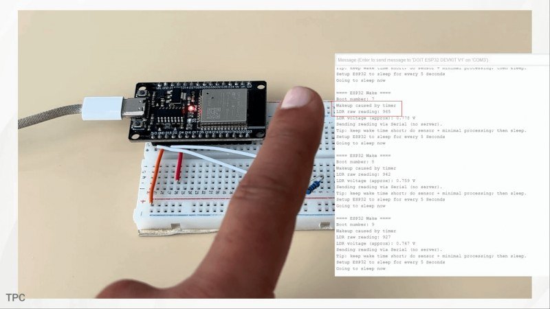
Number 6: Using the deep sleep mode
You can power your IoT projects for months on a single charge by using the deep sleep mode on your ESP32 board. In this mode, the main cores shut down completely, and the chip draws just a few microamps, suitable for battery-powered devices like sensors or wearables.
Apart from this deep sleep mode, there are four other power modes that you can set your ESP32 to:
- Active mode
- Modem sleep mode
- Light sleep mode
- Hibernation mode
Each mode reduces power consumption differently, depending on what peripherals you keep running, for example, Wi-Fi or timers. You can even compare the exact current draw for each mode in the official Espressif datasheet, which shows how dramatically the power usage drops as you move toward deep sleep and hibernation.
But here’s the real pro feature: the ESP32 also has something called the ULP coprocessor, or Ultra Low Power coprocessor. It’s a tiny processor that stays awake even during deep sleep to handle simple tasks like reading a sensor or checking a pin state. So your main chip can sleep for hours, while the ULP quietly monitors your environment
Here’s a simple demo: the ESP32 goes into deep sleep for 5 seconds, wakes up to send the LDR sensor reading, and then goes back to sleep again. This cycle helps you run a project for weeks or even months on a single battery.
You can learn more about this feature in this article.
Code:
#include <WiFi.h>
#include <AsyncTCP.h>
#include <ESPAsyncWebServer.h>

// Replace with your network credentials
const char* ssid = "...................";
const char* password = "......................";

#define POT_PIN 34
#define LED_PIN 32

AsyncWebServer server(80);
AsyncWebSocket ws("/ws");

String potValue = "0";

// HTML + JavaScript
const char index_html[] PROGMEM = R"rawliteral(
<!DOCTYPE html>
<html>
<head>
  <title>ESP32 Real-Time Dashboard</title>
  <style>
    body { font-family: Arial; text-align: center; margin-top: 50px; }
    button { padding: 10px 20px; font-size: 16px; }
  </style>
</head>
<body>

<h2>ESP32 Real-Time Dashboard</h2>

<p>Potentiometer Value:</p>
<h1 id="pot">0</h1>

<button onclick="toggleLED()">Toggle LED</button>

<script>
let ws = new WebSocket(`ws://${location.host}/ws`);

ws.onmessage = (event) => {
  document.getElementById("pot").innerHTML = event.data;
};

function toggleLED() {
  ws.send("toggle");
}
</script>

</body>
</html>
)rawliteral";

// Handle WebSocket events
void onWebSocketEvent(AsyncWebSocket *server,
                      AsyncWebSocketClient *client,
                      AwsEventType type,
                      void *arg,
                      uint8_t *data,
                      size_t len) {

  if (type == WS_EVT_DATA) {
    String msg = "";
    for (int i = 0; i < len; i++) {
      msg += (char)data[i];
    }

    if (msg == "toggle") {
      digitalWrite(LED_PIN, !digitalRead(LED_PIN));
    }
  }
}

void setup() {
  Serial.begin(115200);

  pinMode(LED_PIN, OUTPUT);
  digitalWrite(LED_PIN, LOW);

  WiFi.begin(ssid, password);
  Serial.print("Connecting to WiFi");

  while (WiFi.status() != WL_CONNECTED) {
    delay(500);
    Serial.print(".");
  }

  Serial.println("\nWiFi connected");
  Serial.print("ESP32 IP: ");
  Serial.println(WiFi.localIP());

  ws.onEvent(onWebSocketEvent);
  server.addHandler(&ws);

  server.on("/", HTTP_GET, [](AsyncWebServerRequest *request) {
    request->send_P(200, "text/html", index_html);
  });

  server.begin();
}

void loop() {
  int pot = analogRead(POT_PIN);
  potValue = String(pot);

  ws.textAll(potValue);   // Push value instantly to browser
  delay(100);
}
Number 7: Using the DAC
Most microcontrollers can only output PWM signals, rapid on–off pulses that simulate analog by switching really fast. But PWM is not real analog. It always needs RC filters, smoothing circuits, and even then you still get ripple.
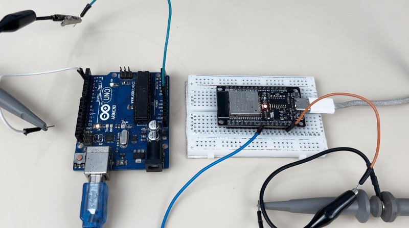
The ESP32 is different. It has two built-in DAC channels on GPIO 25 and 26 that generate true analog voltages from 0 to 3.3V. This means you can produce clean voltage levels, waveforms, or reference signals without any external components, something you simply can’t do on an Arduino Uno or Nano.
Here’s a simple demo: In this first program, I am generating a fixed voltage between 0 and 5V using the PWM technique on Arduino UNO. On the oscilloscope, you’re seeing the output of this PWM signal. You can clearly see the pulses and switching noise on the oscilloscope- this is the ‘fake DAC.’ So there is no fix voltage generated by the board.
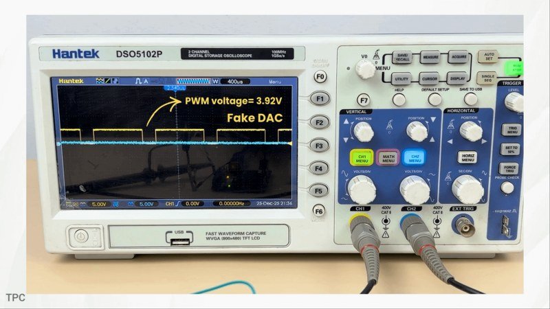
Now look at the ESP32’s DAC signal at the bottom. I am doing the exact same thing here but using the built-in DAC. No pulses, no flicker, just clean analog output straight from the pin.
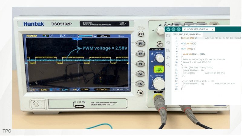
That’s why ESP32 is a very good choice for audio experiments, analog control circuits, and anything where you need a real voltage instead of PWM pulses.
Code (for Arduino):
void setup() {
  pinMode(3,OUTPUT);

}

void loop() {
analogWrite(3,200);
/*analogWrite(5,200);
delay(10);
analogWrite(5,0);
delay(10);*/
/* for (int i=0; i<255; i++){
   analogWrite(3, i);
   delay(50);     //write on DAC Pin
 }*/

}
Code (for ESP32):
#define DAC1 25

void setup(){}

void loop() {

  dacWrite(DAC1, 200);
/*
* here we are using 8 bit DAC so 2^8=255
* Means 0 = 0V and 255=3.3V
*/
 /*for (int i=0; i<255; i++){
   dacWrite(DAC1, i);
   delay(50);
 }*/

 /*for (int i=255; i>=0; i--){
   dacWrite(DAC1, i);          //write on DAC Pin
 }*/
}
Number 8: Coexistence
ESP32 supports both Wi-Fi and Bluetooth, including classic Bluetooth and Bluetooth Low Energy (BLE). But what makes it truly impressive is that it can actually run both of them at the same time, this is called coexistence. It means your ESP32 can send data to the cloud using Wi-Fi, while simultaneously communicating with nearby devices over BLE.
This combination makes it ideal for projects like smart home hubs, health monitoring devices, or industrial sensors, where you might collect data from multiple BLE devices and then send it over Wi-Fi to a server or dashboard.
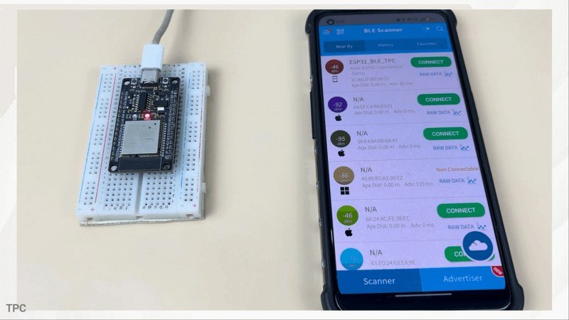
Here’s the simplest example you can actually build. The ESP32 connects to my Wi-Fi network and prints the IP address on the serial monitor. And at the same time, it’s broadcasting a Bluetooth Low Energy device name in the background.
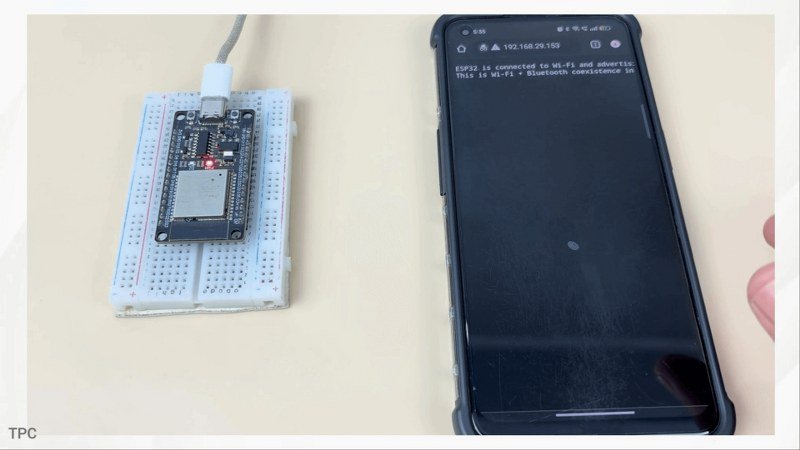
If I open a BLE scanner app on my phone, you’ll see the ESP32 appear instantly, even though it’s already connected to Wi-Fi. That’s coexistence in action: both radios running together smoothly.
Code:
#include <WiFi.h>
#include <WebServer.h>
#include <BLEDevice.h>
#include <BLEServer.h>
#include <BLEUtils.h>

// Replace with your network credentials
const char* ssid = "..................";
const char* password = "............................";

#define BLE_DEVICE_NAME "ESP32_BLE_TPC"

WebServer server(80);

void handleRoot() {
  server.send(200, "text/plain",
              "ESP32 is connected to Wi-Fi and advertising BLE at the same time.\n"
              "This is Wi-Fi + Bluetooth coexistence in action.");
}

void setup() {
  Serial.begin(115200);
  delay(1000);

  // ---- Wi-Fi ----
  WiFi.begin(ssid, password);
  Serial.print("Connecting to Wi-Fi");
  while (WiFi.status() != WL_CONNECTED) {
    delay(500);
    Serial.print(".");
  }

  Serial.println("\nWi-Fi connected");
  Serial.print("IP Address: ");
  Serial.println(WiFi.localIP());

  // ---- Web Server ----
  server.on("/", handleRoot);
  server.begin();
  Serial.println("HTTP server started");

  // ---- BLE ----
  BLEDevice::init(BLE_DEVICE_NAME);
  BLEServer *pServer = BLEDevice::createServer();

  BLEService *pService =
      pServer->createService("12345678-1234-1234-1234-1234567890ab");
  pService->start();

  BLEAdvertising *pAdvertising = BLEDevice::getAdvertising();
  pAdvertising->addServiceUUID(pService->getUUID());
  pAdvertising->setScanResponse(true);
  pAdvertising->start();

  Serial.println("BLE advertising started");
}

void loop() {
  server.handleClient();  // keeps web page responsive
}
Number 9: Security
When you start building real IoT projects, the most important thing is security. The moment your project connects to the internet, security becomes the real challenge. Now let me show you how the ESP32 helps solve this problem using this example.
Here, the ESP32 is not connecting to a normal website using HTTP. Instead, it’s connecting to an HTTPS server, which means all communication happens over an encrypted connection.
First, the ESP32 connects to Wi-Fi. But before it sends or receives any data, it does something very important. It checks who it’s talking to.
The ESP32 has a trusted security certificate stored inside it, which we add in the code. Think of this certificate like a list of trusted authorities, similar to what your web browser uses. When the ESP32 contacts the server, the server presents its digital ID. The ESP32 verifies that ID using the certificate it already trusts.
If the identity doesn’t match, the connection is immediately rejected. This single step prevents fake servers, Wi-Fi spoofing, and man-in-the-middle attacks.
Once the server is verified, the ESP32 performs a TLS handshake. This is a secure negotiation where both sides agree on encryption rules and generate secret keys. From this moment onward, all communication is encrypted.
Even if someone intercepts the data, they’ll only see meaningless, scrambled information.
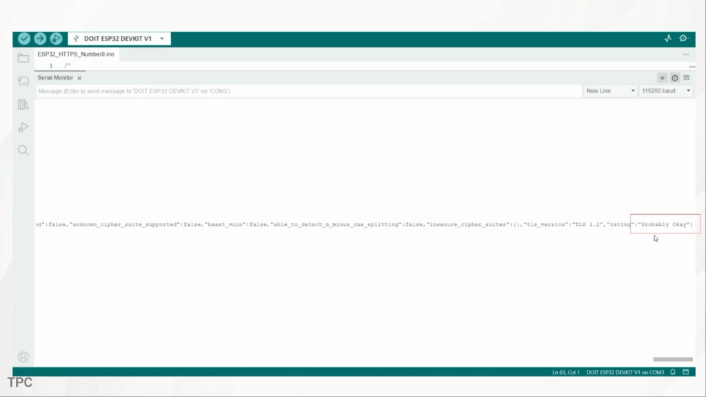
Only after this secure channel is established does the ESP32 send the actual HTTP request. Now here’s where the Serial Monitor output becomes really interesting. When you see: [HTTPS] GET… code: 200
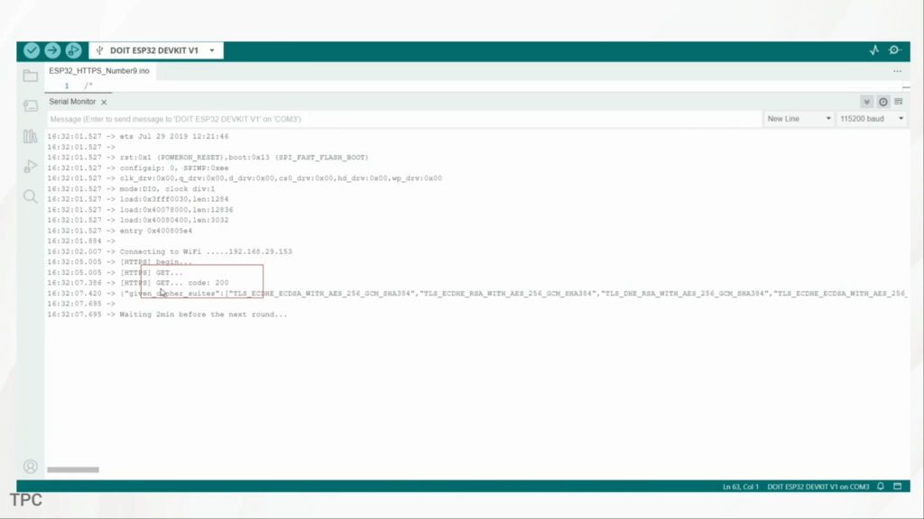
That’s not just a success message. It means:
- The certificate check passed
- The TLS handshake succeeded
- A secure, encrypted channel was fully established
And this final line saying “Probably Okay” is the server’s verdict, confirming that the ESP32’s connection is secure enough for normal internet use. This is exactly how real cloud platforms, banking apps, and smart home devices communicate.
Now here’s why this matters for real IoT projects. If you’re sending sensor data, controlling relays, or managing home automation devices, insecure communication is dangerous. Without encryption, attackers could read your data, inject fake commands, or even take control of your device.
#include <WiFi.h>
#include <AsyncTCP.h>
#include <ESPAsyncWebServer.h>

// Replace with your network credentials
const char* ssid = "...................";
const char* password = "..........................";

#define POT_PIN 34
#define LED_PIN 32

AsyncWebServer server(80);
AsyncWebSocket ws("/ws");

String potValue = "0";

// HTML + JavaScript (served by ESP32)
const char index_html[] PROGMEM = R"rawliteral(
<!DOCTYPE html>
<html>
<head>
  <title>ESP32 Real-Time Dashboard</title>
  <style>
    body { font-family: Arial; text-align: center; margin-top: 50px; }
    button { padding: 10px 20px; font-size: 16px; }
  </style>
</head>
<body>

<h2>ESP32 Real-Time Dashboard</h2>

<p>Potentiometer Value:</p>
<h1 id="pot">0</h1>

<button onclick="toggleLED()">Toggle LED</button>

<script>
let ws = new WebSocket(`ws://${location.host}/ws`);

ws.onmessage = (event) => {
  document.getElementById("pot").innerHTML = event.data;
};

function toggleLED() {
  ws.send("toggle");
}
</script>

</body>
</html>
)rawliteral";

// Handle WebSocket events
void onWebSocketEvent(AsyncWebSocket *server,
                      AsyncWebSocketClient *client,
                      AwsEventType type,
                      void *arg,
                      uint8_t *data,
                      size_t len) {

  if (type == WS_EVT_DATA) {
    String msg = "";
    for (int i = 0; i < len; i++) {
      msg += (char)data[i];
    }

    if (msg == "toggle") {
      digitalWrite(LED_PIN, !digitalRead(LED_PIN));
    }
  }
}

void setup() {
  Serial.begin(115200);

  pinMode(LED_PIN, OUTPUT);
  digitalWrite(LED_PIN, LOW);

  WiFi.begin(ssid, password);
  Serial.print("Connecting to WiFi");

  while (WiFi.status() != WL_CONNECTED) {
    delay(500);
    Serial.print(".");
  }

  Serial.println("\nWiFi connected");
  Serial.print("ESP32 IP: ");
  Serial.println(WiFi.localIP());

  ws.onEvent(onWebSocketEvent);
  server.addHandler(&ws);

  server.on("/", HTTP_GET, [](AsyncWebServerRequest *request) {
    request->send_P(200, "text/html", index_html);
  });

  server.begin();
}

void loop() {
  int pot = analogRead(POT_PIN);
  potValue = String(pot);

  ws.textAll(potValue);   // Push value instantly to browser
  delay(100);
}
Number 10: DMA
One of the most underrated features of the ESP32 is its support for DMA (Direct Memory Access). Normally, when you send data to a display, a speaker, a camera, or even fast sensors, the CPU gets heavily involved and your project starts lagging.
But with DMA, the ESP32 can transfer huge amounts of data directly between memory and peripherals without using the main CPU at all.
This is what makes animations on TFT displays smooth, what lets you play audio through I2S, and what allows high-speed sensors to run without blocking your code. It’s a feature you usually find in much more powerful processors, but the ESP32 gives it to you for free.
The two most important areas where DMA shines on the ESP32 are:
- SPI DMA – perfect for TFTs, OLEDs, LED matrices
- I2S DMA – ideal for audio playback, microphones, and even some cameras
With DMA handling the heavy lifting, your main cores stay almost completely free.