Last updated on March 27th, 2024 at 12:42 pm
BC458 is a general-purpose NPN transistor used in many electronics projects and devices. BC548 transistor is used for amplifying and switching purposes in electrical circuits. Like every other NPN transistor, it consists of three pins: the collector, base, and emitter.
Table of Contents
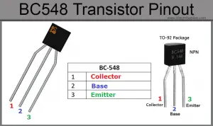
BC548 transistor pinout

| Pin No. | Pin Name | Description |
| 1 | Collector | The flow of current will be through the collector terminal. It is dented by “C” |
| 2 | Base | This pin controls the transistor biasing. It is denoted by “B” |
| 3 | Emitter | The current supplies out through the emitter terminal It is denoted by “E” |
It is a low-cost and widely used transistor. Some other widely used substitutes of BC458 are BC549, BC547, 2N3904, BC108, BC550, BC546, 2N2222,
Features / technical specifications
- Package Type: TO-92
- Transistor Type: NPN
- Max Collector Current (IC): 500mA
- Max Collector-Emitter Voltage (VCE): 30V
- DC Current Gain range (hFE): 110 – 800
- Max Collector-Base Voltage (VCB): 30V
- Max Emitter-Base Voltage (VEBO): 5V
- Low Noise: <10 dB
- Max. Collector Dissipation (Pc): 625 milliwatt
- Max Transition Frequency (fT): 150 MHz
- Max Storage & Operating temperature Should Be: -55 to +150oC

Working states OR modes of operation of BC548
Like every other transistor BC548 transistor works in three regions:
- Cut off Region.
- Saturation Region.
- Active Region

(a) Cut-off region
In the cut-off region, the transistor works as an open circuit or open switch. The base, collector, and emitter currents are all zero in this region. In the cut-off region, both the collector and emitter junctions are reverse-biased. Hence in the cut-off region, the base, emitter, and collector current are zero. This gives
IC=IE=IB=0
here IC = collector current, IE = emitter current, and IB = base current.
(b) Saturation region
In the saturation region, the transistor works like a short circuit or closed switch. The collector and Emitter currents are maximum in this region. In the saturation region, both the collector and emitter junctions are forward-biased. In other words, the transistor operates as a short circuit or closed switch carrying maximum current which implies:
IC=IE
here IC = collector current and IE = emitter current.
(c) Active region
The active region lies between the cut-off and saturation regions. In the active region, the transistor emitter junction is forward-biased and the collector junction is reverse-biased. In the active region, the collector current is β times the base current, i.e.,
IC=β IB
here, IC = collector current
Β = current amplification factor
IB = base current
So the collector current increases in proportional to the base current.
BC548 transistor as a switch
The regions responsible for a transistor to work as a switch are the Saturation Region and the Cut-off Region. When we apply a high enough current at the base of the transistor, it makes a path for the collector current to go through the base toward the emitter.
To use the transistor as a switch, it must be driven into the saturation region with enough base current. A transistor operates as a closed switch under the saturation region.

As soon as a positive signal (in the form of voltage and current) is removed across the base of the transistor, the flow of electric current between the collector and emitter becomes zero. And the transistor behaves like an open switch under the cut-off region.

This simply implies if we apply signal (voltage/current) across the collector and emitter but not across the base, the transistor will not work. But a small signal across the base is enough to make it work.
BC548 transistor as an amplifier
A transistor acts as an amplifier by increasing the strength of a weak signal applied at its base. Transistors work as an amplifier in the active region or linear region. The figure given below shows how to use a transistor as an emitter amplifier.

**Image Source: instrumentationtools
In this region, with the increase in the base current, the collector current also increases proportionally according to the formula:
IC=β IB
Here, IC = collector current
Β = current amplification factor
IB = base current
Thus, a small input signal results in a large output, which implies that the transistor works as an amplifier.
Datasheet
BC547 comes in two packages: SMD and TO-92 package respectively.

Click this link to view the entire DATASHEET of BC548
You can find detailed information on BC548 in the datasheet given above. Specifications and characteristics like Absolute maximum ratings, Block diagrams, biasing methods, and package dimensions can be found in the datasheet.
Applications
- Amplification
- Switching
- Oscillators
- Signal Modulation
- Voltage Regulation
- Audio Amplification
- Darlington Pair Configuration
- Light Sensing
- Temperature Sensing
- Logic Gates
FAQs
Can I use BC548 instead of BC547?
Yes, BC547 and BC548 transistors can generally be used interchangeably in applications such as small-signal amplification, switching, oscillators, signal modulation, voltage regulation, and audio amplification. The major difference between them is that BC547 has a higher breakdown voltage than BC548.
What is the maximum voltage of the BC548 transistor?
The maximum collector-emitter voltage (Vce) for the BC548 transistor is typically around 30 volts DC.