Capacitors are everywhere in electronics, but not all of them do the same job. Even though decoupling, bypass, and coupling capacitors often look identical from the outside, each one has a very specific purpose in a circuit.
Beginners commonly mix them up, and even experienced hobbyists sometimes use the terms interchangeably — which leads to confusion when troubleshooting or designing circuits.
In this article, we will break down the exact roles of these three capacitors, where they are used, how they affect a signal, and why choosing the right one can make or break your circuit.
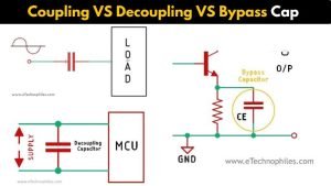
Coupling VS Decoupling VS Bypass capacitor differences
| Feature | Decoupling Capacitor | Bypass Capacitor | Coupling Capacitor |
|---|---|---|---|
| Primary Purpose | Stabilizes the supply voltage and reduces noise caused by sudden current spikes | Provides a low-impedance path for AC noise to ground | Blocks DC while allowing AC signals to pass |
| What It Passes | DC | DC | AC |
| What It Blocks | High-frequency AC noise | High-frequency AC noise | DC |
| Connection Type | Parallel with power supply lines (Vcc–GND) close to IC pins | Parallel across emitter resistors, supply rails, or noisy nodes | Series in the signal path |
| Typical Placement | Near every IC’s power pin (Vcc to GND) | Across RE in CE amplifiers, or across power rails to remove AC | At the input/output of amplifier stages or between two circuits |
| Main Application | Digital circuits, microcontrollers, logic ICs | Amplifiers, analog stages, power rails | Audio circuits, op-amp stages, communication circuits |
| Typical Value Range | 0.01 µF – 0.1 µF (for high-frequency), 1 µF – 100 µF (for bulk stability) | 1 µF – 100 µF (low-frequency), 0.01 µF – 1 µF (high-frequency bypassing) | 1 µF – 10 µF for audio, depends on input impedance |
| Effect on Circuit | Reduces voltage dips, noise, and improves reliability | Removes AC or noise at the emitter/supply line → improves gain or stability | Prevents DC shifts, protects stages from unwanted DC bias |
| Also Known As | Local decoupler, high-frequency decoupler | AC bypass capacitor | DC-blocking capacitor |
Decoupling Capacitor: A decoupling capacitor is used to stabilize the voltage of a circuit by filtering out any noise or ripple voltage that may be present in the power supply.
It is commonly used in digital circuits to reduce the effect of sudden current spikes caused by switching ICs. This is important because when a digital IC switches states, it momentarily draws a sharp burst of current. Without a nearby decoupling capacitor, this causes voltage dips or noise on the supply line, leading to malfunction.
Decoupling capacitors act as a local energy reservoir for ICs: they smooth out supply fluctuations, reduce high-frequency noise, and ensure a stable Vcc/GND reference.
Bypass Capacitor: A bypass capacitor is used to provide a low-impedance path for AC signals to bypass a portion of a circuit.
It is commonly used in power supply circuits to reduce voltage fluctuations and improve the overall stability of the circuit. Bypass capacitors shunt high-frequency noise to ground, preventing it from entering sensitive parts of the circuit.
Note: In practical electronics, bypass and decoupling capacitors are the same component—the difference is how you describe their function.
- When the goal is removing AC noise to ground, we call it bypass.
- When the goal is stabilizing an IC’s supply voltage, we call it decoupling.
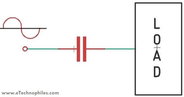
Coupling Capacitor: A coupling capacitor is used to transfer AC signals from one circuit to another while blocking DC signals.
It is commonly used in audio circuits to prevent any DC voltage from being introduced into the audio signal. If a DC signal gets amplified, it can shift the bias point or damage speakers. By using a coupling capacitor, the AC signal can be transferred without any interference from the DC voltage.
Coupling capacitors help transfer AC signals while blocking DC signals, which is important for audio circuits and many amplifier stages where you want to pass only the AC component.
Decoupling capacitor in a circuit
The term Decoupling means Isolation! Decoupling capacitors are used to decouple or isolate two different circuits; in other words, the decoupling capacitor is used for decoupling AC signals from DC signals (this AC signal can be high-frequency noise that is generated by any other circuits).
Note: Technically, decoupling capacitors do not isolate AC from DC like coupling capacitors do. Instead, they absorb high-frequency noise and supply transient current to the IC, preventing that noise from spreading through the power rail.
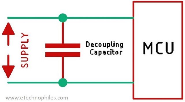
In a digital circuit a decoupling capacitor becomes very important! Suppose a logic circuit that has 5V logic level. Now if there is noise or transient in the supply voltage it will trigger the logic circuit to consider that transient as a high or low signal and that could ruin your day in a pretty bad way, hence the DC Coupling capacitors are widely used for logic circuits.
Note: These capacitors are placed as close as possibl to the IC’s power pins to supply instant current during switching and prevent the supply rail from dipping.
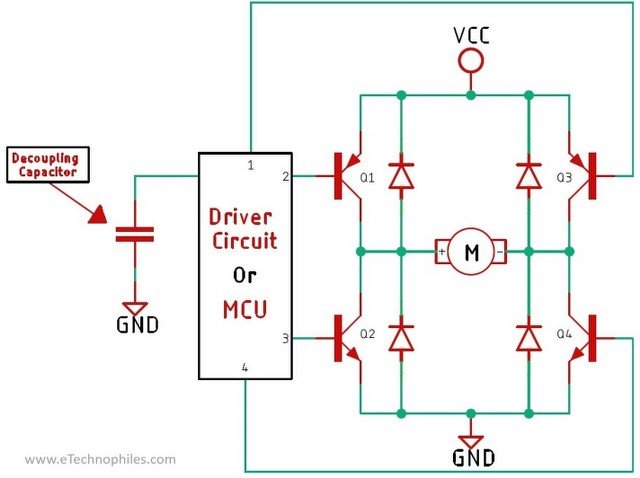
Another good example would be this transistor driven H-bridge circuit that you can find in almost any robotic based projects.
Now let’s consider a situation where you have finalised your prototype and built a PCB for it. Now in the circuit if you didn’t put a decoupling capacitor there is a good chance that the circuit will not function properly due to the noise and harmonic generated by the motor.
Note: Motors generate back-EMF spikes and high-frequency switching noise, and without decoupling capacitors this noise travels back into the power line and affects the logic circuitry.
In this type of situation a decoupling capacitor becomes very important otherwise you will observe random behaviour in your circuit. The capacitors that are used to smooth this high frequency noise are ceramic capacitors.
Ceramic capacitors are preferred because they have very low ESR and excellent high-frequency performance, unlike electrolytics.
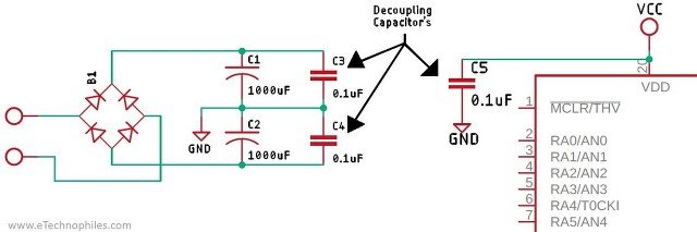
Another great example of a decoupling capacitor is this dual polarity power supply which is mostly used for powering high power amplifiers. In the above image you can see that to improve the output filtered DC signal small bypass capacitors are used to reduce the high frequency noise that can stay even after a large capacitor is used.
Note: This combination of a large electrolytic capacitor + a small ceramic capacitor is called bulk + high-frequency decoupling, and it is standard practice in power supply filtering.
When it comes to selecting decoupling capacitors, there aren’t any hard and fast rules like there are for bypass capacitors. However, because decoupling capacitors are so commonly used in electronic circuits, there’s a general rule of thumb that you can follow. For low-frequency noise decoupling, capacitors with values between 1 µF to 100 µF are typically recommended.
Note: These are often electrolytic or tantalum capacitors and act as bulk storage to maintain overall supply stability.
On the other hand, for high frequency noise decoupling, capacitors with values between 0.01 µF to 0.1 µF are usually preferred.
Note: A very common value is 0.1 µF (100 nF) placed close to each IC’s Vcc pin because it targets switching noise in the 1–100 MHz range.
Bypass capacitor in a circuit
A bypass capacitor has two applications, depending on the placement of the capacitor. First, it prevents noise from entering the system. Second, it acts as a short-circuit path for AC signals in specific circuits.
In power rails, it “bypasses” high-frequency noise to ground. In amplifier stages, it bypasses the AC signal around a resistor to change the gain.
Bypass capacitors are commonly used in amplifiers, digital logic circuits, and power supplies to improve signal integrity, and it also reduces electromagnetic interference. Now let’s look at a practical circuit.
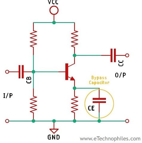
In the above circuit, we have a Common Emitter (CE) amplifier with an Emitter Resistance (RE). The way this is arranged so that the circuit will have a reduced gain at low frequencies, while allowing the gain to remain high at higher frequencies.
Without the capacitor, RE provides negative feedback and reduces gain at all frequencies. When you add the bypass capacitor, it removes this feedback only for AC, restoring gain at mid and high frequencies.
This happens because the capacitor provides a low-impedance path for AC signals to ground, effectively shorting out any signals that are present on the emitter above a certain frequency, thus reducing the overall gain of the amplifier and increasing the overall efficiency for the overall frequency range.
The capacitor shorts the emitter at high and mid frequencies, so the gain increases at those frequencies. At low frequencies, its reactance is high, so the gain drops again.
Now the question is: How do I choose a bypass capacitor? Is there any formula for selecting a bypass capacitor?
The answer to this question is Yes, and it’s very simple to do so. As a general rule of thumb, we can say the reactance of the capacitor in our circuit (the CE capacitor) should be 1/10th or less of the resistance in parallel with it, which is the RE in our circuit. To calculate the reactance of the capacitor, we can use the following formula:
Xc = 1/2πfC
Where,
XC = Capacitive Reactance,
f = Frequency,
C = Capacitance.
With the above formula, let’s try to calculate the value of the CE capacitor from the above circuit. Now, let’s assume the resistor is 560 Ω, and we know the reactance value should be 1/10th of the resistor value, so it becomes 56 Ω. Now if we consider an input frequency of 50 Hz, the bypass capacitor value can be calculated as:
C = 1 / (2 × 3.14 × 50 × 56)
If we do the calculation, it comes out to around 0.00005686988 F or 56 µF. Using the formula shown above, you can calculate the value of the bypass capacitor that can be used in this circuit.
Coupling capacitor in a circuit
The decoupling and bypass capacitor are connected in parallel to the signal in order to pass the AC component of the signal directly to ground. The coupling capacitor filters DC and allows the AC signal to pass through by being connected in series with the signal path.
Coupling capacitors are widely used in amplifier circuits, RF circuits, power supply and many more applications.
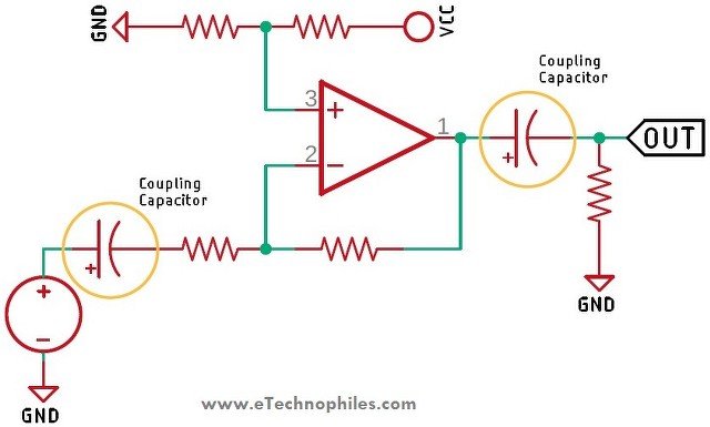
In a single-supply op-amp–based amplifier where it is used to amplify an AC signal, the non-inverting input needs to be biased to a reference voltage; otherwise, the negative part of your signal will be cut off. In circuit biasing, this means the non-inverting pin is supplied with half of the supply voltage.
In this type of circuit, the DC voltage that is introduced in the signal also gets amplified, and this can cause some major problems if that op-amp is being used as a preamplifier to drive a power amplifier. To remove the DC part of the signal, coupling capacitors are used. Coupling capacitors are usually placed at the input or output of the circuit, but they can also be used in between staged amplifiers.
Now, as we have learned about all three types of capacitors and how they work, let’s summarise all that in this part of the article. When we are talking about decoupling and bypass capacitors, they allow DC to pass through while blocking AC, while a coupling capacitor allows AC to pass through and blocks DC. A bypass or decoupling capacitor is used in parallel to the power line, and if we are talking about coupling capacitors, they are placed in series with the circuit.