In electric and electronics engineering, accuracy and reliability are critical. To diagnose, test, and troubleshoot circuits efficiently, engineers rely on specialized measurement tools. This article highlights nine essential tools, explaining their uses and the key features to consider when selecting them for your toolkit. If you are a beginner, you will find this article really helpful.
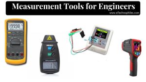
Measurement tools for engineers
1. Multimeter

A multimeter is a versatile instrument that can measure multiple electrical properties, including voltage (AC/DC), current, resistance, and continuity. It’s an essential tool for detecting and diagnosing faults in circuits.
Modern digital multimeters offer advanced features such as auto-ranging, data hold, and even temperature measurement, which make them invaluable for both simple and complex tasks.
Key Features to Look For:
- Auto-ranging to save time during measurement.
- Continuity testing with a buzzer to easily check closed circuits.
- Capacitance measurement and diode testing for working with electronic components.
A multimeter is indispensable for tasks like verifying power supplies, testing batteries, and identifying faulty connections in circuits.
2. Oscilloscope

An oscilloscope measures and displays electrical signals as waveforms over time, allowing engineers to observe voltage changes and analyze the performance of circuits. Oscilloscopes are particularly useful for inspecting AC signals, transient voltages, and digital communication protocols.
By showing signal behavior in real-time, they help engineers troubleshoot issues like noise, signal distortion, or timing errors.
Key Considerations:
- Bandwidth: Select an oscilloscope with a bandwidth that exceeds the highest frequency of the signals you’ll measure.
- Sampling rate: Higher sampling rates provide more detailed waveforms.
- Trigger functionality: Look for advanced triggering options to capture specific events.
An oscilloscope is essential for projects involving communication protocols, digital systems, and high-frequency circuits.
3. Multifunction Tester

A multifunction tester, also known as the ‘LCR tester’ is designed to measure the characteristics of various components, including inductance (L), capacitance (C), and resistance (R), as well as transistors and MOSFETs. This tool provides quick insights into the health and functionality of these components.
For engineers working with analog circuits or repairing electronic devices, it offers a convenient way to check multiple parameters without needing separate instruments.
Important Features:
- Automatic component recognition, which speeds up testing.
- Wide measurement ranges for inductance, capacitance, and resistance.
- Ability to test active components like transistors, diodes, and MOSFETs.
A multifunction tester is crucial for validating component functionality in both prototype development and repair work.
4. Logic Analyzer

A logic analyzer is used to capture and analyze digital signals across multiple channels, making it ideal for debugging communication protocols, microcontrollers, or digital circuits. Engineers use logic analyzers to study timing relationships between digital signals and to identify glitches or timing errors in communication buses like I2C, SPI, or UART.
Key Considerations:
- Number of channels: Choose a logic analyzer with enough channels for the signals you need to monitor simultaneously.
- Sample rate: Ensure the analyzer has a high enough sampling rate for the digital signals you’re working with.
- Protocol decoding: Built-in decoding features for protocols like I2C, SPI, and UART streamline the debugging process.
Logic analyzers are essential when dealing with microcontroller-based systems, communication buses, and complex digital logic circuits.
5. Clamp Meter

A clamp meter allows for non-invasive current measurement by clamping around a conductor to measure current without physically disconnecting it. This is particularly useful for measuring high currents or in situations where breaking the circuit is not practical. Clamp meters are often used in industrial settings or for diagnosing electrical panels and large-scale circuits.
Modern clamp meters offer the full functionality of a multimeter, with the added advantage of measuring current through the clamp without breaking the circuit
Important Features:
- AC/DC current measurement: Ensure the meter can handle both alternating and direct current.
- Inrush current detection: Useful for measuring peak currents in motors and other inductive loads.
- Additional functionality: Some clamp meters also measure voltage, resistance, and frequency, making them versatile tools.
Clamp meters provide a quick and safe way to measure current, especially in systems where breaking the circuit can be dangerous or inconvenient.
6. Logic Probe

A logic probe is a handheld tool used to test the logic levels of digital circuits. It indicates whether a signal is high (logic 1), low (logic 0), or pulsing, providing a fast and straightforward way to check digital signals in a circuit.
Unlike a logic analyzer, which provides detailed timing information, a logic probe offers a quick, basic check of signal states. Can be really helpful while debugging circuits and PCBs.
Key Considerations:
- Responsiveness: Ensure the probe reacts quickly to changes in signal state.
- Durability: Choose a sturdy probe that can withstand frequent use.
- Compatibility: Check that the probe is designed to work with the voltage levels used in your circuits.
Logic probes are useful for quick diagnostics in simple digital circuits or during breadboard prototyping.
7. Tachometer

A tachometer is used to measure the rotational speed (RPM) of motors or rotating components. It is particularly important in projects involving motors, robotics, or mechanical systems where precise control of rotational speed is necessary.
Engineers use tachometers to ensure motors are running at the desired speed or to diagnose issues in mechanical systems.
Key Features to Look For:
- Contact vs. non-contact: Non-contact tachometers use optical methods to measure RPM without physical contact, ideal for fragile or high-speed systems.
- Measurement range: Ensure the tachometer’s RPM range covers the speeds you’ll be working with.
- Accuracy: Look for a tachometer with high accuracy to ensure reliable measurements.
Tachometers are critical in applications like motor control, robotics, and any system with rotating machinery.
8. Signal Generator

Although this is not a measurement tool, you can use it to test your own circuits. A signal generator produces precise electrical waveforms, such as sine, square, and triangle waves, which can be injected into circuits for testing.
This tool is essential for evaluating the performance of filters, amplifiers, and other signal processing circuits by providing consistent, controllable signals.
Key Factors to Consider:
- Frequency range: Ensure the generator covers the frequency range of your applications.
- Modulation capabilities: For advanced projects, look for AM, FM, or phase modulation options.
- Waveform variety: The ability to generate multiple types of waveforms for different circuit tests.
A signal generator is particularly useful for testing circuits that rely on signal integrity, such as communication systems and audio electronics.
9. Thermal Imaging Camera

Thermal imaging cameras allow engineers to visualize heat patterns in circuits. Overheating components can indicate excessive current draw, faulty power supplies, or inadequate heat dissipation. With a thermal camera, engineers can quickly identify hot spots that are invisible to the naked eye, preventing component damage and ensuring long-term reliability.
Key Features:
- High thermal sensitivity to detect minor temperature variations.
- Wide temperature range to monitor a variety of components.
- Real-time heat mapping to pinpoint problem areas.
Thermal imaging is particularly valuable in power electronics, where overheating can cause failures, and in systems with high-power components like transformers and voltage regulators.
Conclusion
Accurate measurement is essential in electrical and electronics engineering, and the tools you choose play a crucial role in ensuring success. Whether you’re testing a simple circuit or debugging a complex system, these nine tools will provide the insights you need to diagnose, troubleshoot, and refine your designs. By understanding their features and applications, you can select the right tool for the job and ensure your projects run smoothly.